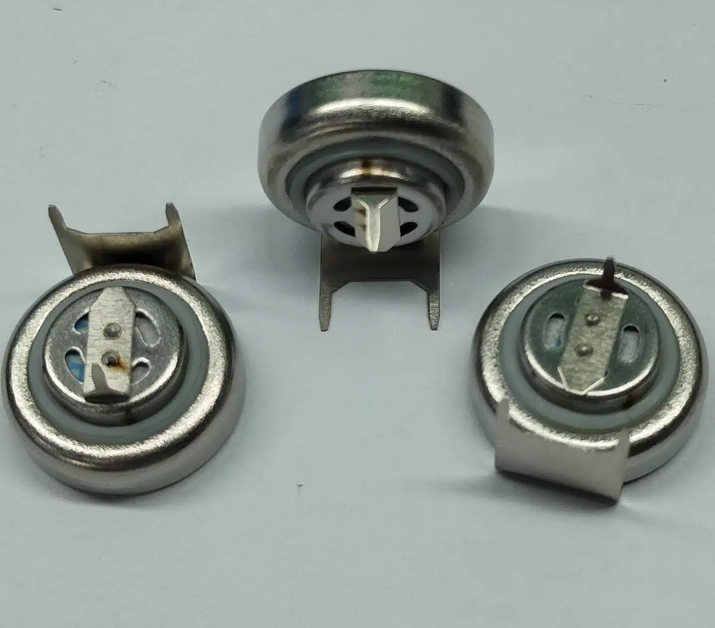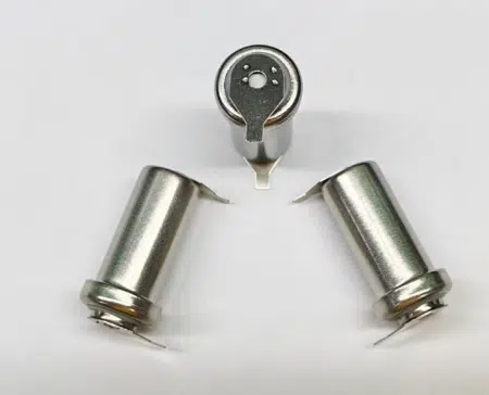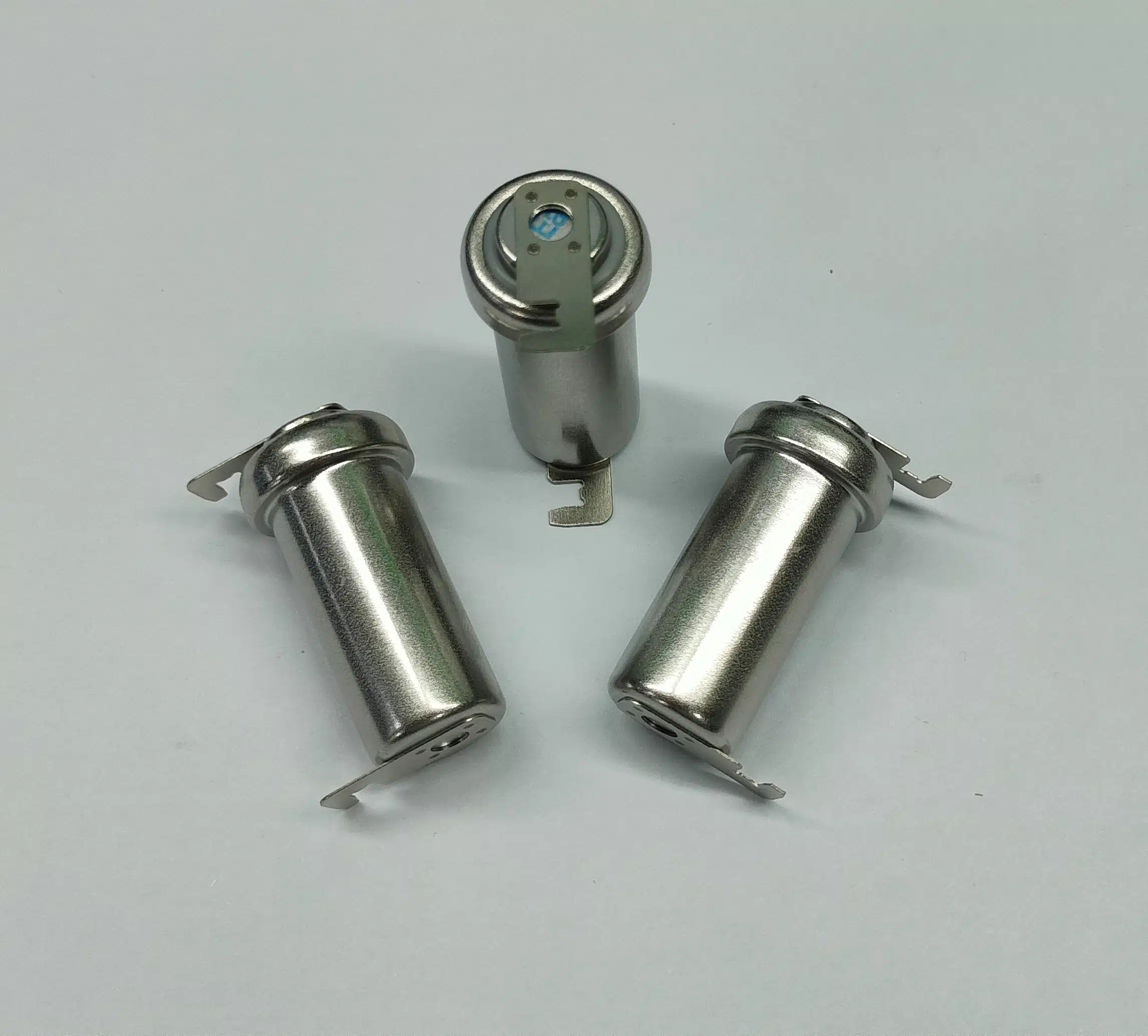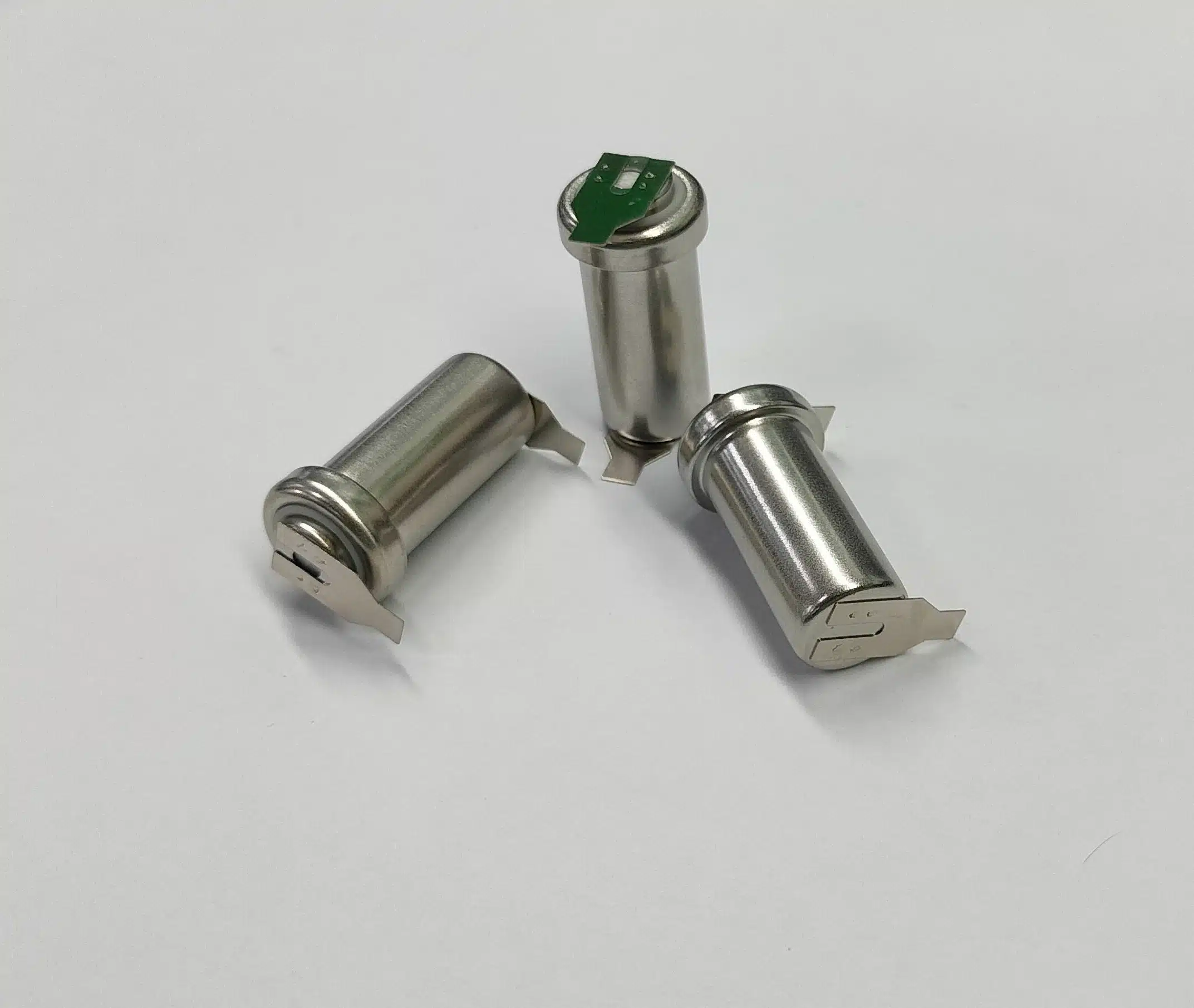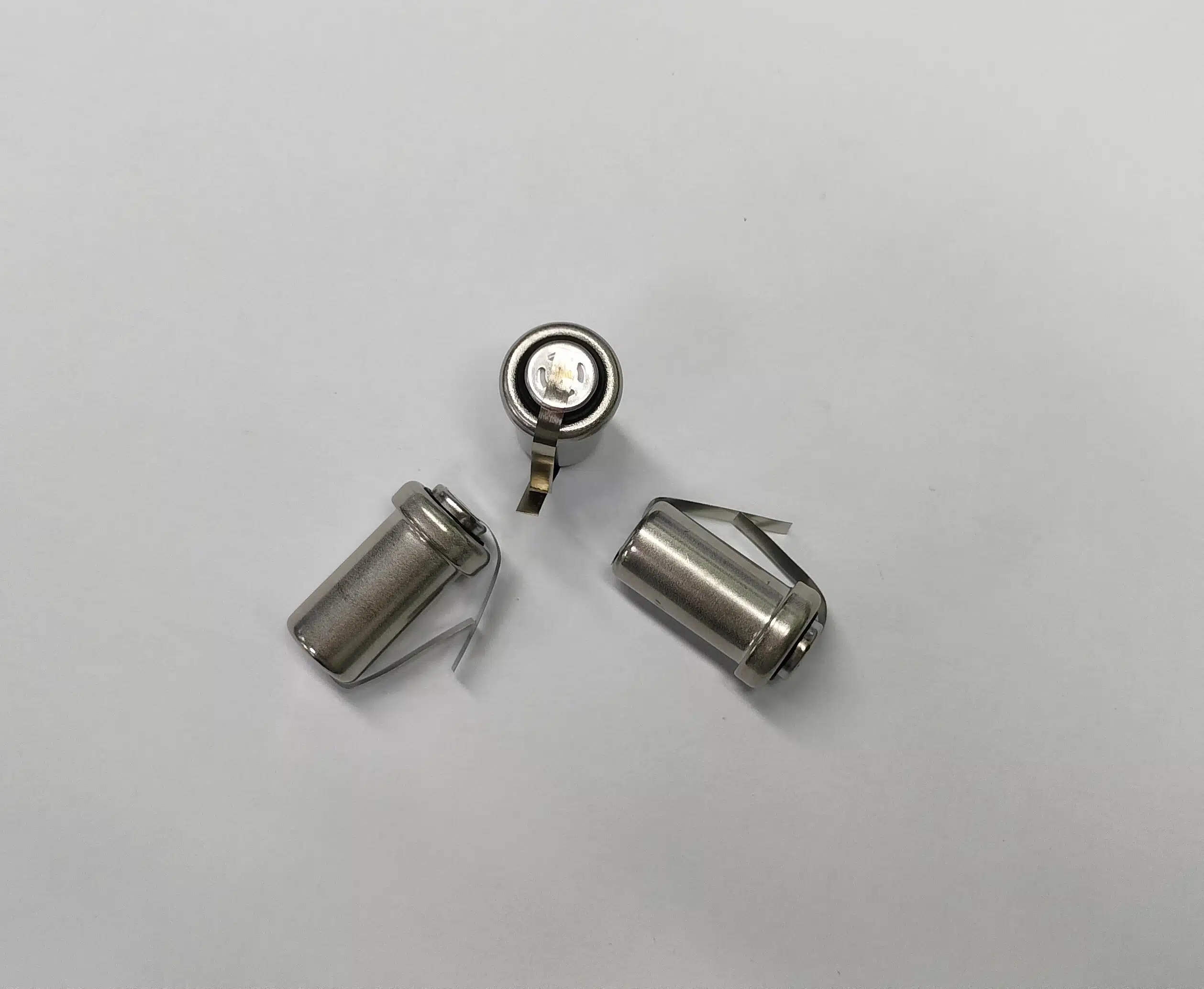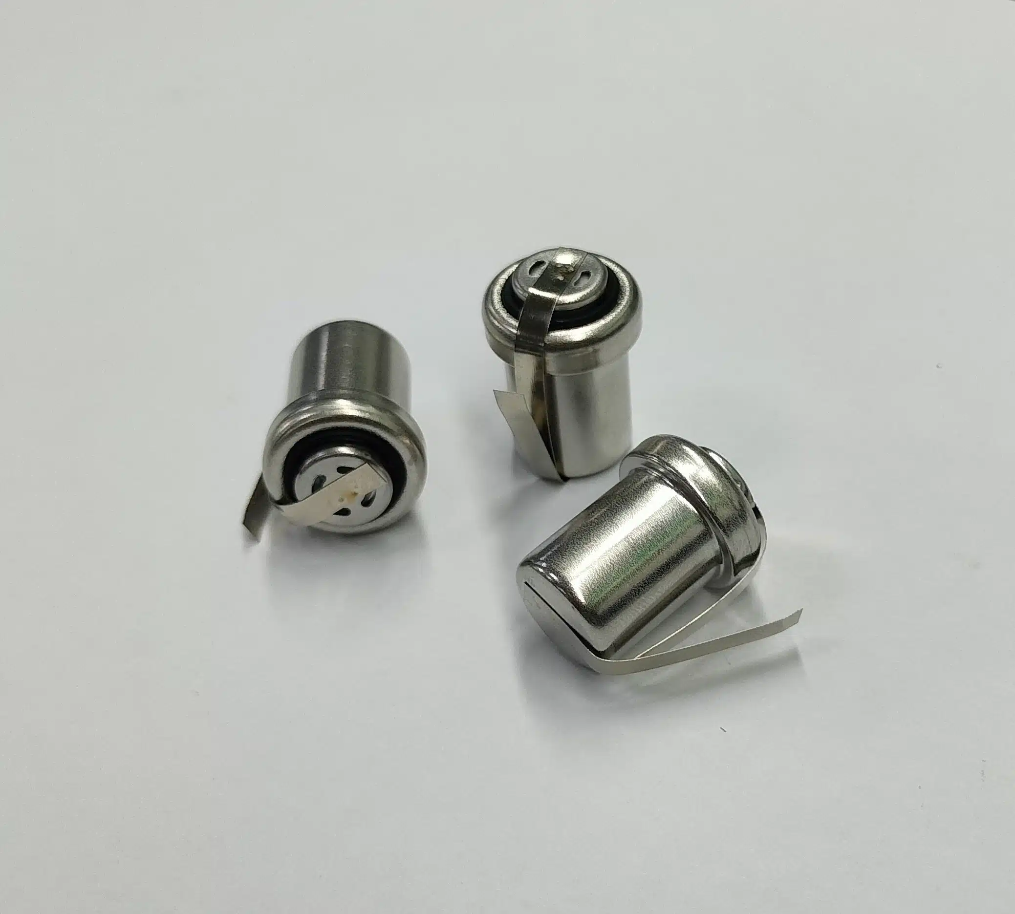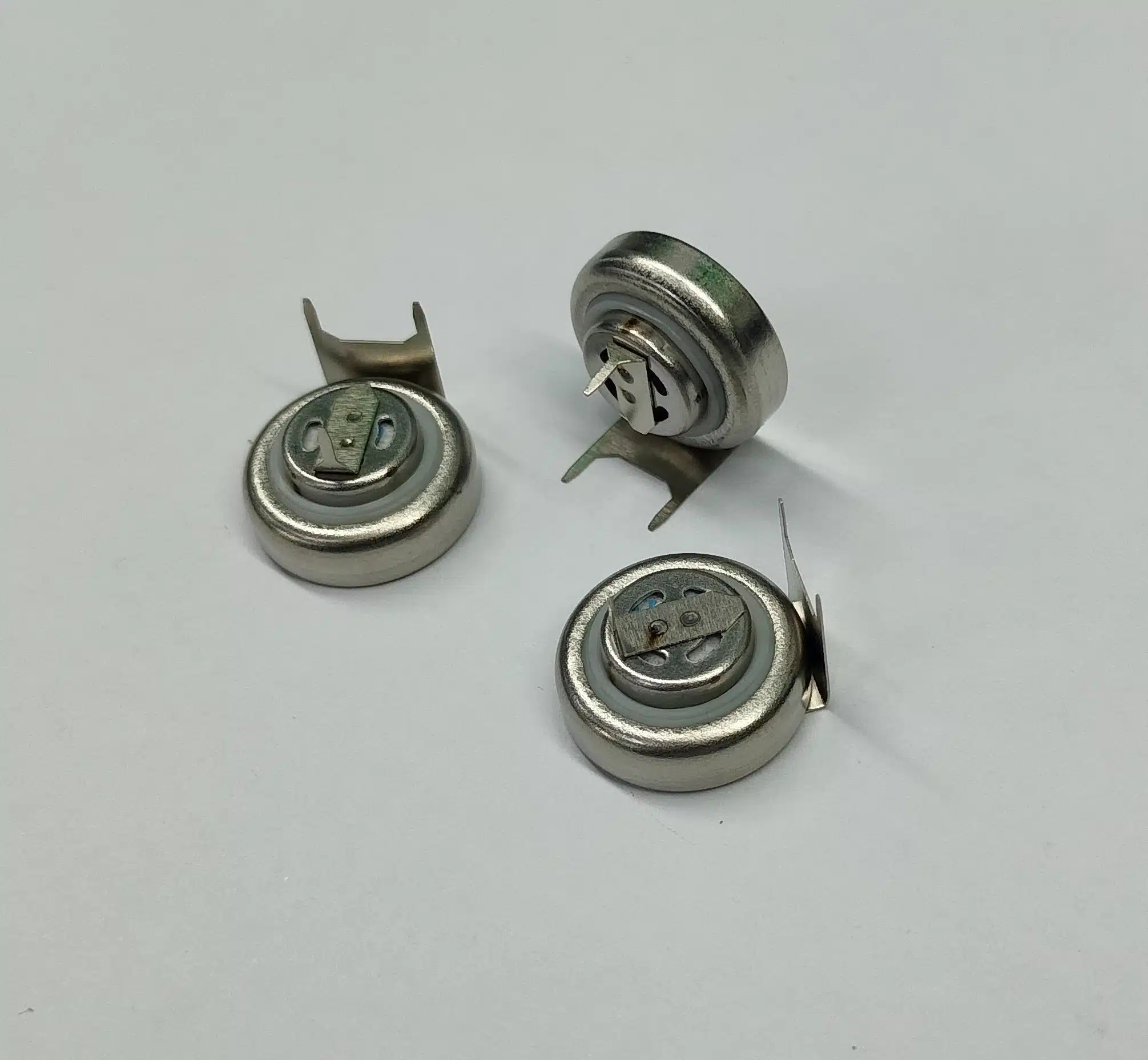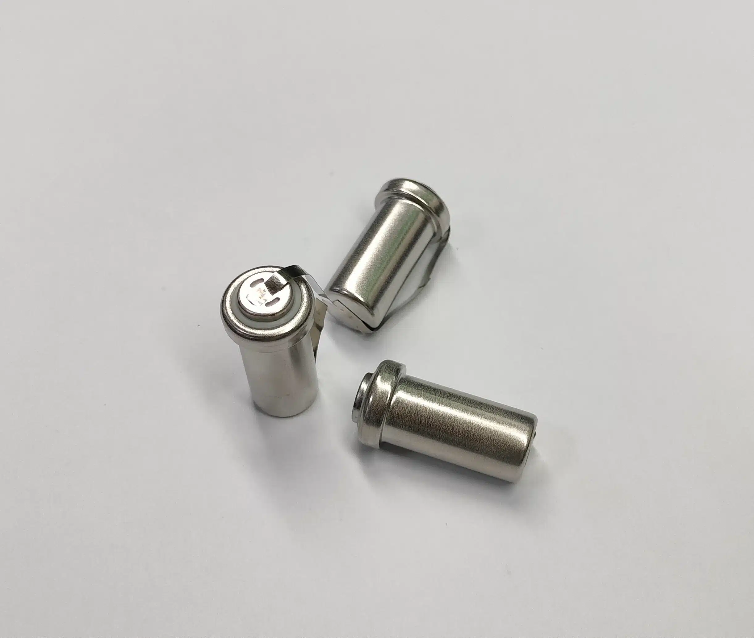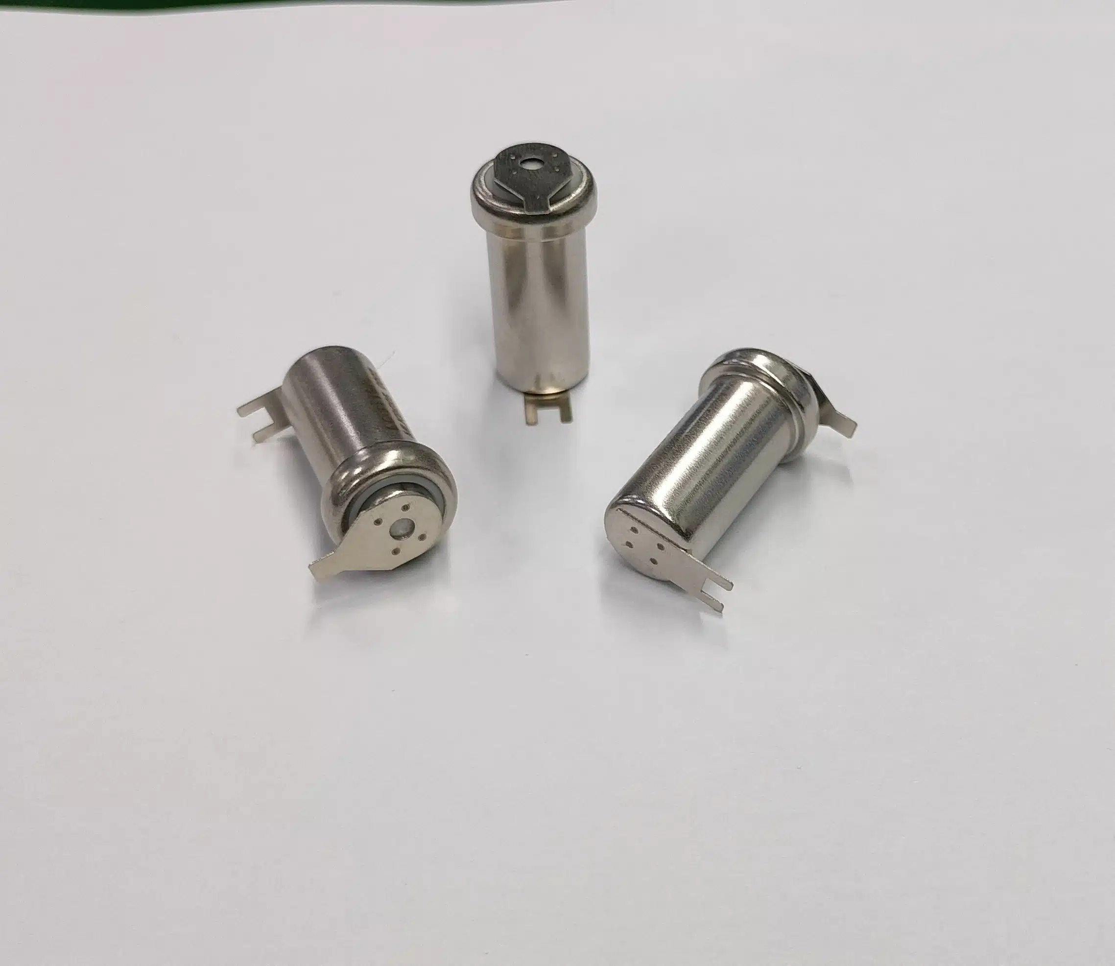
In carbon monoxide alarm projects, many OEM customers assume that “as long as an electrochemical CO sensor is used, the product will definitely be stable and certified.” However, based on over 20 years of experience in European and American projects, this judgment is often incorrect. This blog will provide a detailed introduction to building a correct CO sensor system solution from a developer’s perspective.
Why Electrochemical CO Sensor Projects Still Fail in OEM Applications?
Why do products choosing “electrochemical CO sensors” still fail to pass certification or generate numerous complaints in the market?
In our over 20 years of involvement in CO alarm projects in Europe and America, CFS has observed a typical phenomenon:
Many OEM customers believe: “Using an electrochemical sensor = the product will definitely be stable and will definitely pass certification.”

However, the reality is:
Conclusion: The problem isn’t “whether to use an electrochemical sensor,” but rather “whether this technology is truly understood and engineered for use.” Most CO alarm project failures are not due to sensor issues, but rather the system’s lack of engineering validation in complex environments.
CFS helps you build certificate, stable, mass-production-ready CO detection systems.
👉 Get Your CO Sensor Project Evaluation
Electrochemical CO Sensor ≠ Certified CO Alarm System
An electrochemical sensor is merely a signal source, while an alarm is a complete system:

If these three components are not compatible:
Even if the sensor performs well, it may still fail to pass certification or operate stably.
Top 3 Root Causes of EN50291 & UL2034 Failures
From our 20+ years OEM experience:
- 30% EN50291 failures = alarm curve mismatch
- 35% returned units = no actual defect
- ±20% sensor deviation without calibration
The issue is NOT the sensor itself, but system integration.
How Electrochemical CO Sensors Actually Work
Electrochemical CO sensors detect gas through a controlled chemical reaction:
- CO diffuses into the sensor
- Oxidation occurs at the electrode
- Generates micro-current
- Converted into CO concentration signal
You also can read more: How CO Sensors Work – OEM Guide to Stable CO Detection Systems
Key Performance Parameters OEM Buyers Must Evaluate
Sensitivity & cross-gas interference
According to the relevant experiments conducted under the UL2034 standard’s “Sensitivity Test”(table 1), the standard requires placing the sensor in 20℃ & 40%RH environment and exposing it to different concentrations of carbon monoxide for varying durations in Figure 1. The sensor’s sensitivity was tested before, during, and after exposure using the method specified in UL2034. Throughout the entire exposure test, CO SENSOR (LDCS1511A) exhibited a stable output current signal.
PPM | Exposure time (Minutes) |
|---|---|
30 | 900 |
70 | 240 |
150 | 90 |
400 | 30 |

CO SENSOR (LDCS1511A) was subjected to interference durability testing with various interfering gases according to the specifications of UL2034. The CO sensor was compared using 12 different gases (Figure 2). The other cross-test gases had almost no effect on the sensitivity。 The sensitivity before and after CO gas remained at 0.05 μA(no changing).

CO SENSOR (LDCS1511A) was tested Carbon monoxide in first and last of 12 different gases, the sensitivity is only 3% shift in Figure 3. CO SENSOR (LDCS1511A) exhibits excellent linearity and extremely high stability.

You also can read more: Electrochemical CO Sensor Lifespan Guide
Temperature compensation
Figure 4 shows the temperature dependence of the CO SENSOR (LDCS1511A) in a constant humid environment of 50% RH. The Y-axis represents the ratio of the current output (I) to 400 ppm carbon monoxide at different temperatures to the current output (Io) in 400 ppm carbon monoxide at 20°C/50% RH. The temperature dependence varies depending on the catalytic reaction rate on the electrode and can be easily compensated for by using a thermistor.

Response & recovery time
Figure 5 shows the response and recovery time of the sensor CO SENSOR (LDCS1511A). During testing, the sensor was placed in the test system. Data was recorded in clean air for 5 minutes, then 400 ppm of carbon monoxide standard gas was introduced for 5 minutes, followed by a return to clean air for 5 minutes. This yielded the sensor’s response and recovery time curves. The sensor’s response and recovery time are within 30 seconds of the UL2034 limit.
t1: Response time reaches 90% of the saturation signal level.
t2: Recovery time returns to 90% of the baseline level.

Linearity & repeatability
CO SENSOR (LDCS1511A) output current (mA) is linearly related to the CO concentration, with a deviation of less than ±5% in the range of 0 to 4000 ppm .
| PPM | Output Current(mA) | |||||||||
| No. 1 | No. 2 | No.3 | No. 4 | No. 5 | No.6 | No.7 | No. 8 | No. 9 | No.10 | |
| 0 | 0.0000 | 0.0000 | 0.0000 | 0.0000 | 0.0000 | 0.0000 | 0.0000 | 0.0000 | 0.0000 | 0.0000 |
| 200 | 0.3550 | 0.3340 | 0.3570 | 0.3662 | 0.3350 | 0.3760 | 0.4270 | 0.4066 | 0.3636 | 0.4250 |
| 400 | 0.7150 | 0.6800 | 0.6900 | 0.7080 | 0.6890 | 0.7110 | 0.8300 | 0.8180 | 0.6880 | 0.8560 |
| 600 | 1.1620 | 1.0500 | 1.1120 | 1.1250 | 1.1067 | 1.1680 | 1.2400 | 1.1890 | 1.1150 | 1.2300 |
| 800 | 1.5300 | 1.4450 | 1.4680 | 1.4780 | 1.4098 | 1.5060 | 1.6800 | 1.5200 | 1.4580 | 1.6260 |
| 1000 | 1.8450 | 1.7600 | 1.7780 | 1.7860 | 1.6730 | 1.8040 | 2.1250 | 2.0050 | 1.6860 | 2.1550 |
| 2000 | 3.6300 | 3.5580 | 3.6080 | 3.7607 | 3.4050 | 3.6650 | 4.1550 | 4.1200 | 3.5607 | 4.2355 |
| 4000 | 7.3655 | 7.1450 | 7.3560 | 7.4670 | 7.1550 | 7.4200 | 8.2500 | 8.1550 | 7.2660 | 8.3635 |
When the CO Sensor is repeatedly exposed to 400 ppm carbon monoxide every 240 seconds, the output current is repeatable with a deviation of less than ±2%.
| Output Current(mA) | ||||
| No.1 | No.2 | No.3 | No.4 | |
| Time 1 | 0.782 | 0.798 | 0.855 | 0.72 |
| Time 2 | 0.796 | 0.811 | 0.836 | 0.73 |
| Time 3 | 0.797 | 0.815 | 0.843 | 0.74 |
| Time 4 | 0.799 | 0.813 | 0.849 | 0.75 |
| RSD | 1.0% | 0.9% | 1.0% | 1.8% |
If you are still interested in the sensor performance (including Long-Term Stability ,Stability Testing, High and low temperature operation testing, Transportation and Storage test), please Download CO Sensor Validation Checklist.
Why 30% of CO Alarm Returns Are Not Real Defects
In multiple projects, we found that: Over 30% of returned products had no functional defects.
The real reasons include:
These problems are essential system design issues, not hardware issues.

Engineering Validation Required for Mass Production
Before entering mass production, the following verifications must be completed:
Ensure consistent output from each sensor.

Reduce batch-to-batch variations.
3. Algorithm Verification
Ensure alarm times meet the standard curve.
4. Environmental Testing
Covering real-world usage scenarios such as temperature, humidity, and airflow.
Long-Term Stability: What 3-Year Data Really Means
Long-term test data shows:
- Drift is controlled within approximately 4% over 3 years.
- Output stability meets long-term requirements.
However, it must be emphasized that:
This is the result of “engineering control,” not a natural property of the sensor.
Interference & Environmental Testing Based on UL2034
In interference gas testing:
- Extremely low response to gases such as methane and alcohol
- CO sensitivity change <3%
In environmental testing:
- High and low temperature cycling does not affect output
- Humidity effect is negligible
Note: With proper design, the sensor has good anti-interference capabilities.
From Sensor to System: How to Build a Certifiable CO Alarm
A certified CO alarm system should be:
In other words: You need a “system solution,” not just a single component.

We provide a complete support process:
- Project requirements assessment
- Sensor and solution selection
- Algorithm and system design
- Prototype testing and verification
- Certification support
- Mass production
👉 Ensuring controllable progress from design to mass production
You also can read more: Carbon Monoxide Alarm Compliance Guide
OEM Checklist: How to Reduce Certification Risk
When selecting a supplier or solution, it is recommended to confirm:
If anyone is missing, the project risk increases significantly.
Conclusion: Engineering, Not Component, Determines Success
In CO alarm projects:
- Sensors are just the foundation
- Algorithms determine the response
- Systems engineering determines the outcome
The key to success is not choosing the right components but building the right system. Most CO alarm failures are caused by unvalidated system integration, not sensor quality.
Get Your CO Sensor Project Evaluation
If you are developing CO alarms or evaluating OEM solutions:
👉 Get project evaluation advice
👉 Get customized CO alarm solutions
We can help you:
Related Products