CO Alarm Not Sounding at Low Levels: An OEM Engineering Case Study
A CO alarm that does not sound at a low concentration is not necessarily defective. The assessment must consider the measured CO concentration, exposure duration, and alarm logic of the specific model. For an OEM project, the first step is to distinguish between normal alarm delay and inadequate sensor response, calibration error, or a separate requirement for a low-level warning.
This engineering review covers sensor selection, zero and span calibration, multi-concentration verification, optional low-level warning, fault indication, and baseline management. The design objective is to retain the existing housing and mounting arrangement where practical. Any changes to the sensor, PCB, firmware, or production tests must be assessed for their effect on alarm performance, manufacturing cost, and certification scope. Application suitability must be confirmed for the intended market and installation.
Project Overview
An OEM CO alarm must provide the required concentration-time alarm response, maintain performance within its declared operating conditions and support a documented service-life claim. Low-level display or warning is an additional product requirement and should be evaluated separately from the formal CO alarm.
Traditional electrochemical CO sensors suffer from drawbacks such as sensitivity decay over time, reduced response at low concentrations after long-term use, and baseline drift due to electrolyte depletion. Semiconductor sensors also suffer from saturation, failing to recover their low-concentration detection capability after exposure to high concentrations, ultimately leading to missed alarms. Products on the market perform only single-point calibration and lack aging-compensation logic, meeting standards only in the short term, with performance declining significantly after 2-3 years of use.
Addressing the technical contradictions of traditional products, such as “sensitivity decay → no alarm at low concentrations, single-point calibration → insufficient long-term stability,” this project completes a full-chain upgrade of low-concentration detection software and hardware. It is fully compatible with the original shell, structure, and existing production lines, requiring no new molds and enabling rapid mass production. This provides export companies with a practical, customized solution for EN 50291-compliant CO alarms.
Project Info
Project | Details |
|---|---|
Project Name | OEM CO Alarm Low-Level Response Evaluation and Design Review |
Implementation Time | June 2026 |
Service Model | OEM/ODM solution customization, software and hardware iteration, prototype validation, small-batch trial production, mass production implementation |
Compatible Products | Standalone electrochemical carbon monoxide alarm (residential) |
Sensor Type | Electrochemical CO sensor (all-solid-state electrolyte or gel electrolyte optional) |
Target Market | European and global residential projects |
Design Standards | EN 50291-1:2018, EN 50291-2:2010, CE certification, with RoHS and REACH compliance support |
Deliverables | Optimized prototype, sensitivity test report, sensor calibration data, mass production firmware, selection manual, production line adaptation solution |
Core Optimization Modules | Sensor selection and matching, multi-concentration point calibration, low concentration pre-alarm function, fault self-diagnosis system, dynamic baseline calibration |
Project Implementation Timeline | Requirements review → Original-sample evaluation → Root-cause investigation → Design changes → Prototype validation → Certification-impact review → Pilot production → Production release |

Customer Requirements
The customer reported concerns about low-level CO alarm response in an existing product supplied to the European market. The evaluation needed to establish whether the reported behavior resulted from normal alarm timing, the test method or a performance issue. The customer also requested a review of long-term stability and the feasibility of an additional low-level warning function.
The customer specified three iteration guidelines:
1. Reliable detection at low concentrations: Utilizing sensor selection and multi-concentration calibration, ensure strict compliance with the EN 50291-time window for concentrations of 30ppm, 50ppm, and 100ppm.
2. Long-term stability guarantee: Within a 10-year service life, sensor sensitivity decay is controlled within the standard’s allowable range, mitigating the risk of missed low-concentration detections due to aging.
3. Zero modifications for mass production: The appearance, structure, mounting position, and assembly process should remain the same as in the previous version, without opening new molds or modifying production lines, thereby controlling iteration costs and mass-production risks. Simultaneously, complete sensitivity testing, sensor aging tests, calibration curves, and export compliance documentation are required to ensure the solution is verifiable, replicable, and suitable for mass production.

Smoke and CO detector manufacturer CFS PCBA

Customized optimization scope (five core upgrades)
1. Selection and Matching of High-Stability Electrochemical Sensors
- Focusing on sensor performance, select electrode film catalysts resistant to poisoning to ensure the sensor effectively avoids potential poisoning from automotive exhaust, silicon, fluids, etc., under normal operating conditions.
- Use materials with better sealing performance to ensure the electrolyte will not dry out within 10 years.
- Select sensors based on 100% of their output characteristics, including internal impedance, output parameters, and temperature stability. Coverage includes EN 50291 requirements for 30/50/100/300 ppm test points, T90 response time < 30 s, operating temperature range -20℃~60℃, adaptability to various field installation environments; sensor design life ≥10 years, annual sensitivity decay controlled within 3%.

CO sensor manufacturer CFS

2. Multi-Concentration Calibration and Sensitivity Aging Compensation Algorithm
Traditional CO alarms typically use single-point calibration (50 ppm or 100 ppm), leading to poor accuracy at low concentrations. Since the CO sensor’s range is linearly correlated with CO concentration, this project employs a two-point calibration scheme: zero gas (0 ppm) and a 100-ppm CO standard. These are used to calibrate the baseline and operating point, establishing a complete sensor characteristic curve. After calibration, a 300-ppm test is performed to verify the stability of the calibration curve.
A built-in sensitivity compensation algorithm, based on an aging model, dynamically compensates for the sensitivity decrease caused by catalyst activity decay, using sensor operating time and historical response data. The model compensates for a 3%/year decay trend, ensuring that the sensor’s effective sensitivity remains above 70% of its factory value over a 10-year period. This compensation is a dynamic correction based on the aging trend, not a fixed annual forced-gain addition, thereby avoiding overcompensation for individual sensors. Dynamic temperature compensation is also applied to products operating at both low and high temperatures.

Smoke and CO detector manufacturer CFS High temperature and high humidty

3. Development of Low-Concentration Pre-Alarm Function
In accordance with Annex F of EN 50291-1:2018, which recommends low-concentration early warning, a new low-concentration CO pre-alarm function has been added. A CO concentration of 25 ppm (50% of the 50-ppm alarm threshold) triggers a yellow LED visual warning, prompting the user to ventilate; a concentration of 35 ppm triggers a low-concentration audible and visual warning (distinct from the formal alarm), providing early risk alerts. The pre-alarm function can be enabled or disabled and customized according to the customer’s product positioning. This function provides early risk warnings and enhances terminal safety protection.

Smoke and CO detector manufacturer CFS PCBA test fixture

4. Sensor Fault Self-Diagnosis System
Periodic sensor self-test logic is added to automatically check the sensor’s operating condition every 60 minutes. The self-test includes sensor open/short circuit detection, sensitivity anomaly detection, and baseline offset detection. When the sensor sensitivity is detected to be below 70% of the factory default value, or the baseline offset exceeds ±5ppm, the equipment triggers an independent audible and visual fault indication (distinguished from the CO alarm), reminding the user to replace the entire unit. This addresses the industry pain point of sensor aging and failure without indication, and complies with the EN 50291 self-test and fault-indication requirements.
-
wholesale CO alarms manufacturer CFS

5. Firmware Baseline Calibration Algorithm
At low concentrations, the CO sensor’s output is very low. Therefore, the PCBA firmware has a significant impact on the output of sensors connected to the circuit. Different sensors have different internal impedances and insulation impedances. Therefore, a calibration step is added to the actual manufacturing process to uniformly calibrate the firmware of devices not connected to CO sensors to the same baseline value.

smoke detector and CO detector manufacturer CFS CO calibration

Employing an event-driven + dynamic baseline calibration mechanism: The zero point is automatically calibrated periodically in a clean-air environment, eliminating baseline drift caused by temperature and humidity fluctuations and long-term aging. Built-in temperature and humidity compensation factors correct sensor output in real time, controlling zero-point drift to within ±2 ppm under normal temperature conditions to ensure low-concentration detection accuracy. The firmware integrates sensor saturation detection logic that automatically assesses the sensor’s recovery status after high-concentration CO exposure, preventing low-concentration detection failures following saturation.
Technical Pain Points and Industry Challenges
1. Insufficient Signal-to-Noise Ratio at Low Concentrations: Electrochemical CO sensors output weak nA-level signals in the <50 ppm concentration range, making them highly susceptible to circuit noise, temperature, and humidity disturbances. Noise and drift can be equivalent to concentration deviations of several ppm, directly interfering with low-concentration detection accuracy.
2. Gradual Decline in Sensor Sensitivity: Decreased catalyst activity and electrolyte depletion reduce sensitivity. Long-term exposure of the sensor or alarm to high concentrations of CO, silicon vapor, sulfides, and other pollutants accelerates sensor poisoning and failure. A sensor may require concentrations of 10 ppm or higher to respond now, compared with a 1 ppm change.
3. Saturation Effect from High-Concentration Exposure: After prolonged exposure to high concentrations of CO, the sensor output cannot quickly return to zero. Actual measurements show that after 15 minutes of exposure to 5000 ppm, the sensor’s response to 50 ppm gas recovers to only 40-50% of normal, leading to subsequent failure in low-concentration scenarios.
4. EN 50291 dual compliance threshold: It must meet the mandatory alarm time window requirements of EN 50291-1, while EN 50291-2 has additional testing requirements for motorhome and recreational vehicle scenarios.
Solution Limitations and Risks
Limitations | Description |
|---|---|
Sensor Lifespan Limitation | Electrochemical sensors have a design lifespan of 5-6 years. |
Extreme Environment Limitations | Extreme temperatures below -10℃ or above 50℃ can affect sensor performance |
Sensor Poisoning Risk | Long-term exposure to high silicon vapor and sulfides will accelerate sensor failure |
Certification Responsibilities | This solution completes EN 50291 design verification and pre-testing; final certification of the entire device is the customer’s responsibility, and we provide complete technical documentation and compliance guidance. |
Unsuitable Scenarios | Industrial-grade high-precision CO online monitoring, data acquisition equipment requiring continuous concentration recording, and non-electrochemical detection solutions. |
Compliance Support | The solution supports RoHS and REACH documentation; EN 50291-related testing must be completed during the overall device certification stage; additional hazardous substance requirements for special markets require separate assessment. |
Overall Solution and Verification System
Constructing a four-dimensional low-concentration detection closed-loop system: “Sensor Layer – Calibration Layer – Algorithm Layer – Diagnostic Layer”:
Layer | Optimization Strategy |
|---|---|
Sensor Layer | All-solid-state electrolyte selection + wide temperature range performance matching |
Calibration Layer | Two-point calibration (0ppm + 100ppm) + dynamic sensitivity compensation based on aging model |
Algorithm Layer | Dynamic baseline calibration + temperature and humidity compensation factors; temperature compensation uses piecewise linear fitting, with independent calibration of the temperature coefficient in every 10℃ interval; humidity compensation is based on real-time correction of the RH sensor, with a compensation accuracy within ±1ppm |
Diagnostic Layer | Periodic self-diagnosis + sensitivity anomaly detection + saturation recovery assessment |
Complete verification test matrix
Test Item | Test Condition | Judgment Criteria |
|---|---|---|
30 ppm Non-Alarm Verification | 25℃, Standard Pressure, 120min Continuous Exposure | No audible or visual alarm triggered |
50ppm Alarm Time Test | 25℃, Standard Pressure, Continuous Exposure | Alarm triggered within 60-90 minutes |
100ppm Alarm Time Test | 25℃, Standard Pressure, Continuous Exposure | Alarm triggered within 10-40 minutes |
300 ppm Alarm-Time Test | 25℃, Standard Pressure, Continuous Exposure | Formal alarm activation within the applicable maximum time; record individual sample results. |
Sensitivity Annual Decrease Simulation Test | Accelerated aging, equivalent to 10 years of use | Sensitivity decrease ≤30% |
High Concentration Saturation Recovery Test | 5000ppm × 15min | Clean air recovery within 60 minutes and Response recovery ≥90% |
High and Low Temperature Cyclic Test | -17.8℃~66℃*10 cycles | Alarm time deviation within the standard allowable range |
Transportation and Storage | -40℃*168H, 70℃*168H, 25℃*24H | CO output deviation before and after comparison test ≤3% |
High and Low Temperature Output | In an environment of 150 ppm, the CO output was recorded after being placed at 10°C for 2 hours at each 10°C interval from -20°C to 70°C | The change was ≤3% |
Small-batch trial production verification: The appearance, assembly, and existing production lines are 100% compatible with the old version, eliminating the need for new molds and reducing the risk of mass production iteration.
Data comparison before and after optimization
Item | Original Solution (Pre-optimization) | Optimized Solution |
|---|---|---|
Calibration Method | Single-point calibration | Two-point calibration + aging compensation |
30ppm Response | Record formal alarm activation or non-activation under the specified exposure. Identify any supplementary indication separately. | Record formal alarm activation or non-activation under the specified exposure. Identify any supplementary indication separately. |
50ppm Alarm Time | Occasional timeouts; high variance | Stable control within the 60–90 minutes |
100ppm Alarm Time | timing is inconsistent (10–40 minutes) | timing is inconsistent (10–40 minutes) |
300ppm Alarm Time | Alarms, but with high timing variance | ≤90 seconds |
Annual Sensor Sensitivity | <3%; no aging compensation | <2%; includes aging compensation |
Sensor Fault Diagnosis | None | Periodic self-diagnosis + fault indication |
Recovery from High-Concentration Saturation | Slow recovery or permanent failure | Recovers to >80% within 60 minutes |
Baseline Drift Control | >±5ppm | Within ±2ppm |
Validation Findings and Project Status
1. Technical Achievements
- Validation distinguishes the non-alarm requirement at 30 ppm from alarm timing at 50, 100 and 300 ppm. Results apply to the tested hardware and firmware version.
- The ten-year service-life target requires supporting sensor data and complete-unit validation. Short-term test results are not presented as ten years of field performance.
- Proposed warning settings require validated timing, indication and reset behavior before release.
- Diagnostic coverage is limited to the faults supported and validated by the design.
- Zero-point performance is evaluated under defined environmental conditions and baseline-adjustment limits.
2. Compliance Achievements
Meets the EN 50291-1:2018 full-concentration alarm time window, completing design verification and pre-testing, supporting the customer’s whole-machine certification; compatible with EN 50291-2 recreational vehicle additional requirements, with supporting RoHS/REACH documentation; EMC-related testing completed during the whole-machine certification stage.
3. Mass Production Results
Utilizing existing molds and assembly processes, zero investment in mold development, low iteration risk, rapid deployment, and adaptability to OEM orders of varying sizes.
4. Value
- Reduces safety hazards and customer complaints caused by false CO alarms in European apartments and property projects.
- Low-concentration pre-alarm as a differentiated selling point, setting it apart from competitors that only meet basic compliance requirements.
- Sensor fault self-diagnosis avoids safety incidents caused by end-users being unaware of equipment failure.
- Standardized and replicable low-concentration CO detection solutions shorten customers’ new product development cycles.
CFS supports CO alarm engineering evaluation, prototype development and validation planning. Available reports depend on the model and project stage. Third-party testing can be arranged within the agreed development scope.
-
Smoke and CO detector manufacturer CFS PCBA assembly

Request Type | Service Details |
|---|---|
Information Request | Full sensitivity test reports, sensor calibration data, product selection guides |
Prototype Testing | Prototype optimization requests, small-batch trial production verification |
OEM/ODM Cooperation | Sensor selection and customization, firmware development, algorithm tuning |
Certification Support | Design guidance based on EN 50291 standards, pre-test compliance support |
Export Compliance | CE certification documentation, RoHS and REACH compliance reports |
Volume Quotation | MOQ, lead times, mass production scheduling plans |
FAQ
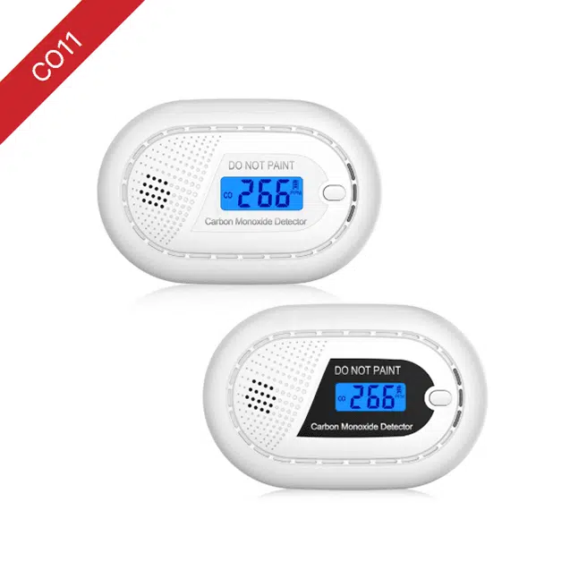
CO11 Standalone Carbon Monoxide Alarm
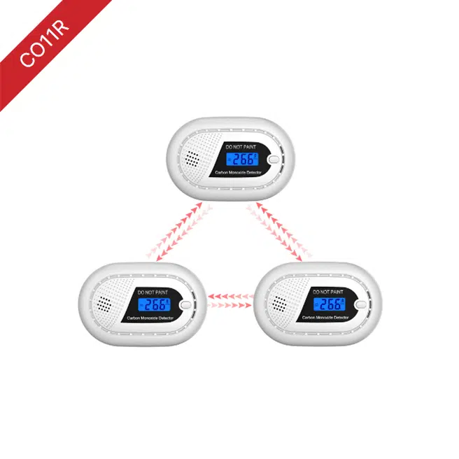
CO11R Wireless Interlinked Carbon Monoxide Alarm
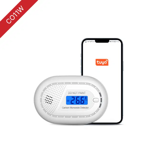
CO11W WIFI Carbon Monoxide Alarm

CO12 Standalone Carbon Monoxide Alarm
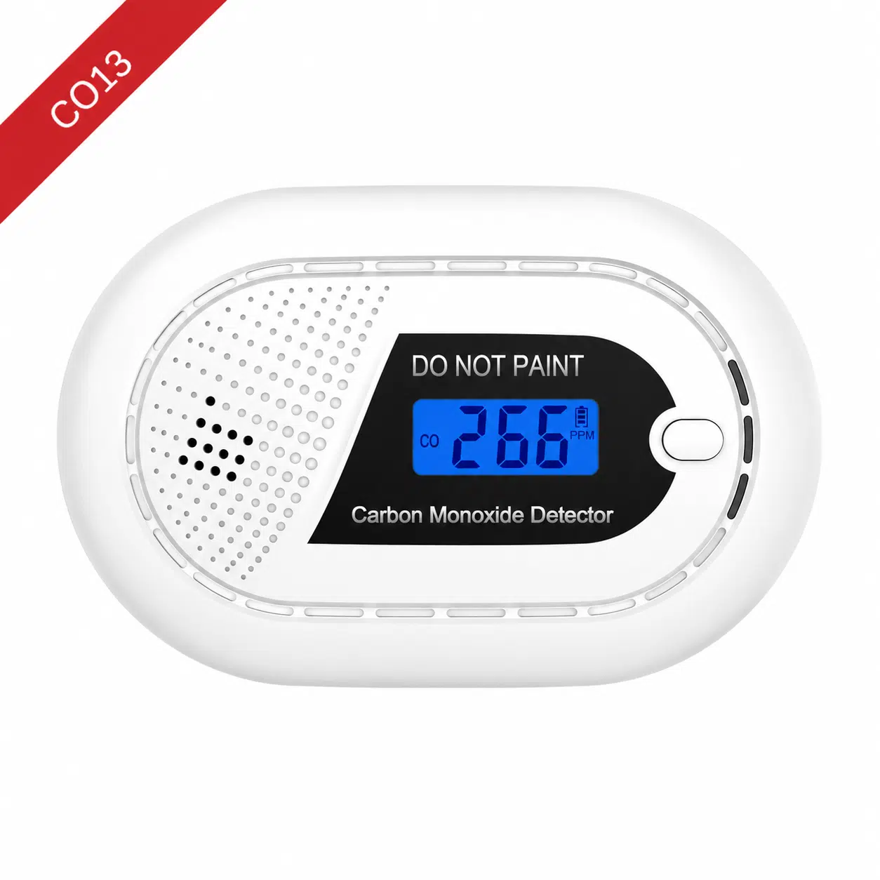
CO13 Standalone Carbon Monoxide Alarm
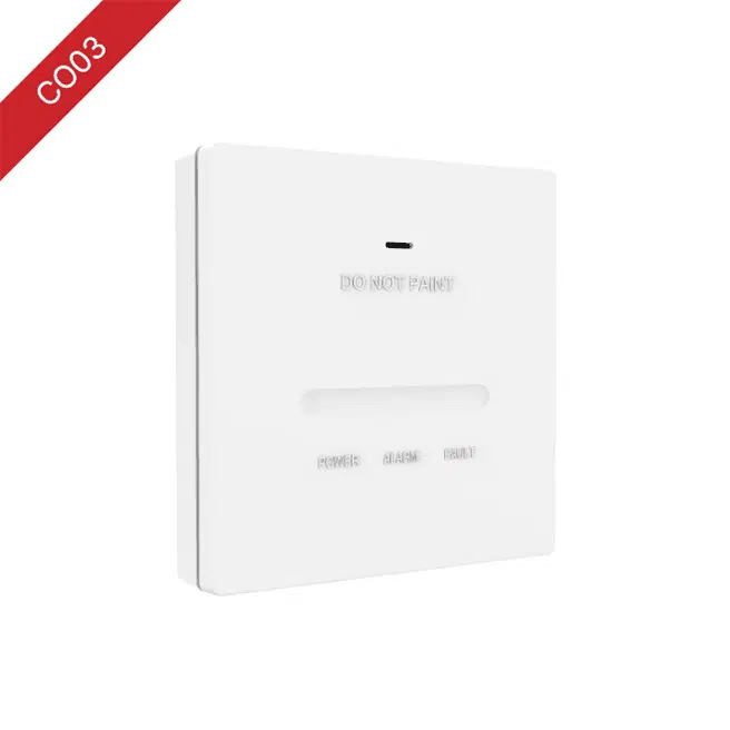
CO03 Standalone Carbon Monoxide Alarm
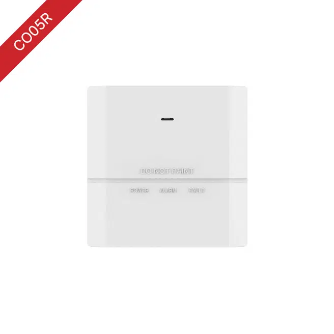
CO05R Wireless Interlinked Carbon Monoxide Alarm
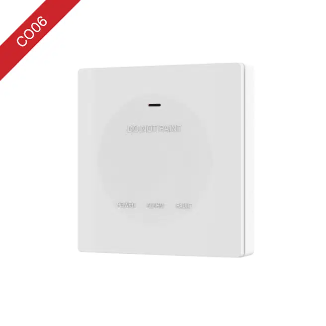
CO06 Standalone Carbon Monoxide Alarm
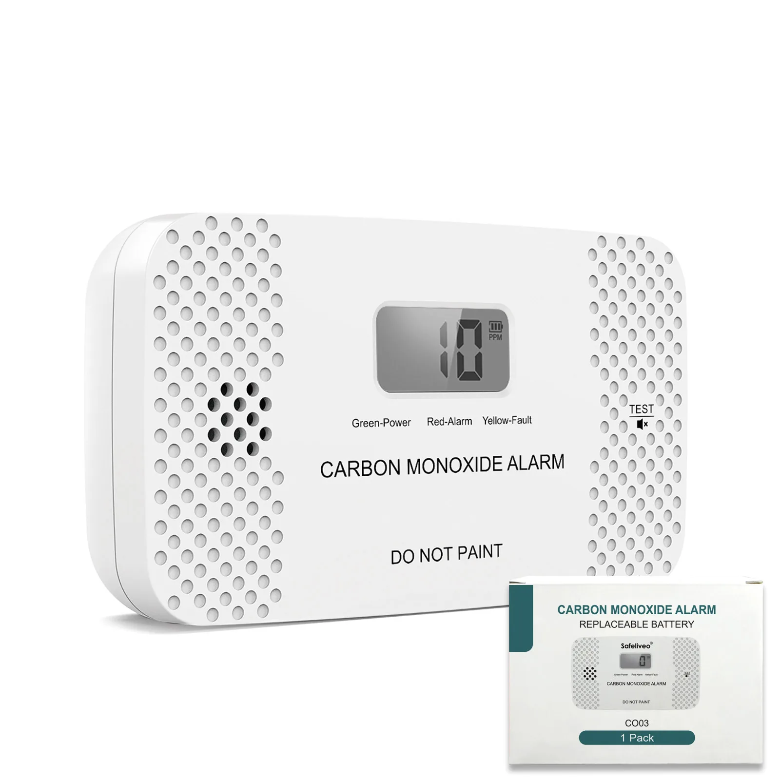
CO07 Standalone Carbon Monoxide Alarm
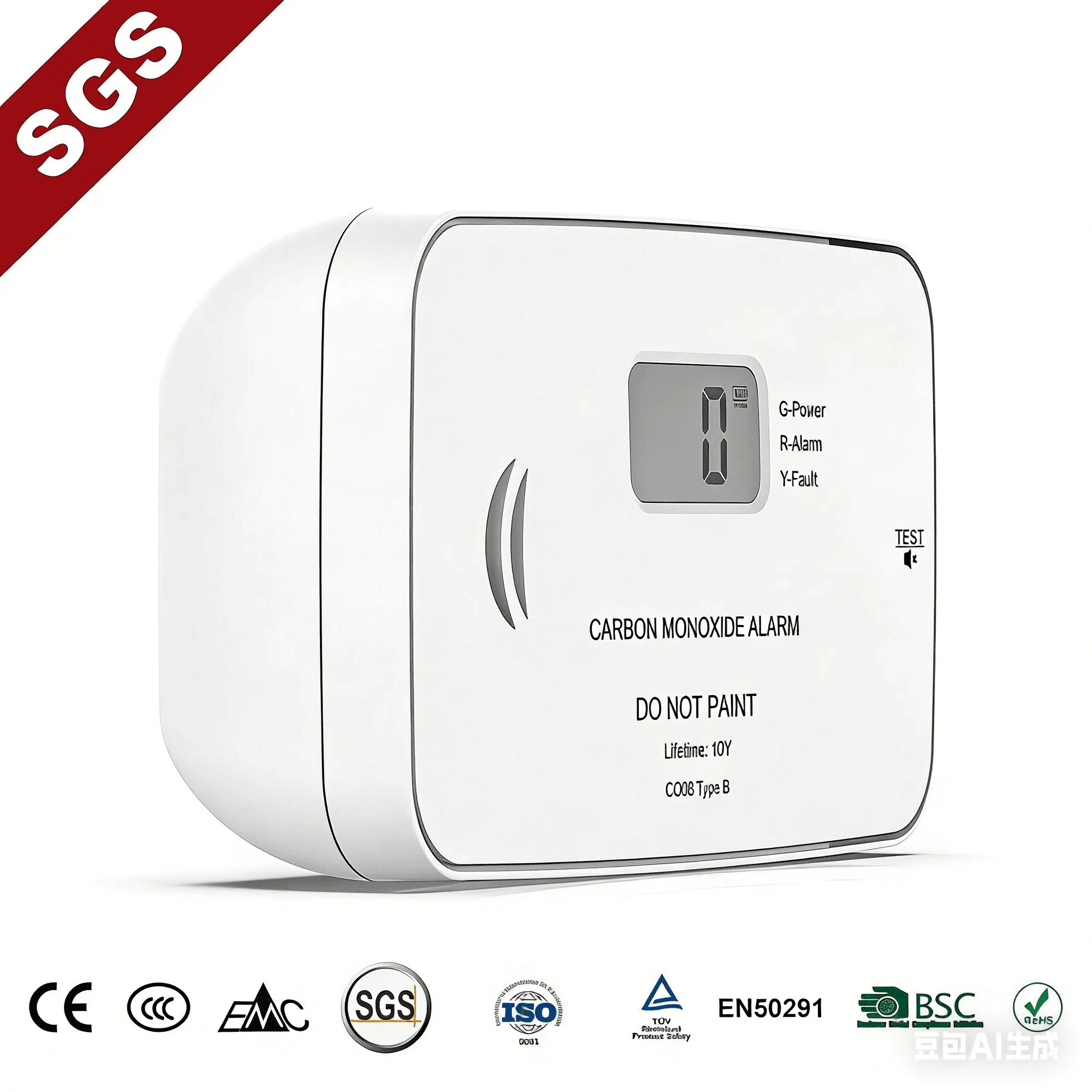
CO08 Standalone Carbon Monoxide Alarm
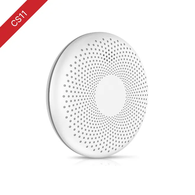
CS11 Standalone Smoke And Carbon Monoxide Combo Alarm
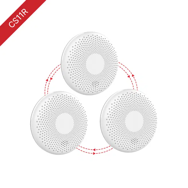
CS11R Wireless Interlinked Smoke & Carbon Monoxide Combo Alarm

CS11W WIFI Smoke And Carbon Monoxide Combo Alarm
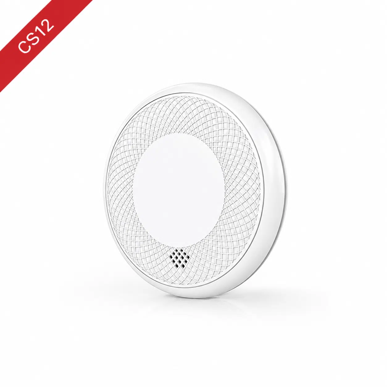
CS12 Standalone Smoke And Carbon Monoxide Combo Alarm
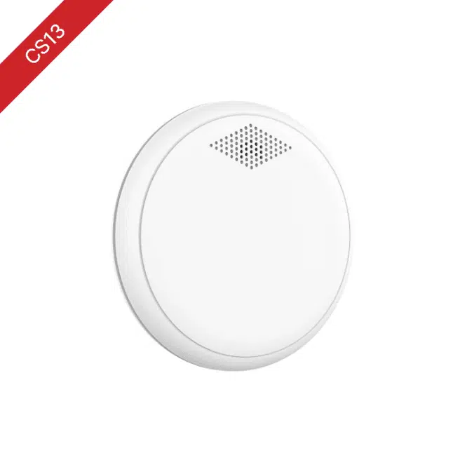
CS13 Standalone Smoke And Carbon Monoxide Combo Alarm
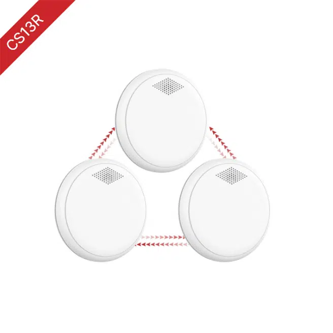
CS13R Wireless Interlinked Smoke And Carbon Monoxide Combo Alarm
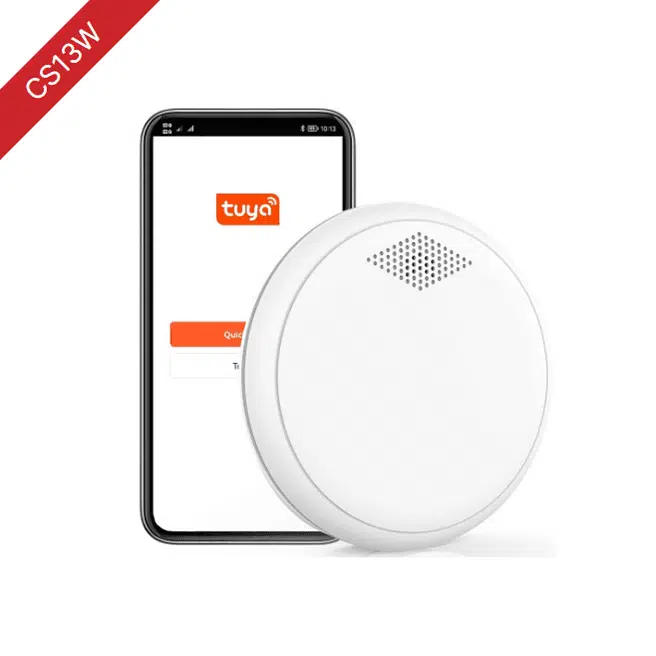
CS13W WIFI Smoke And Carbon Monoxide Combo Alarm
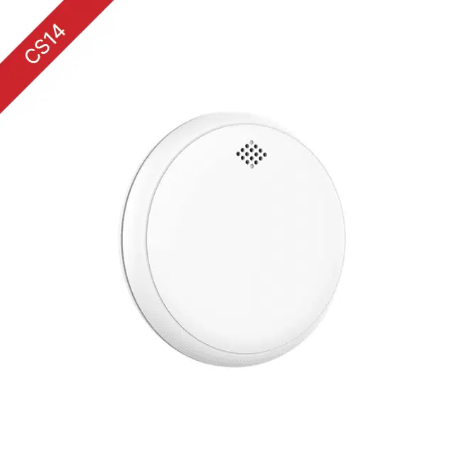
CS14 Standalone Smoke And Carbon Monoxide Combo Alarm
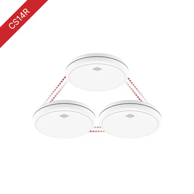
CS14R Wireless Interlinked Smoke And Carbon Monoxide Combo Alarm